iranMadar-SmallLogo
Search
Close this search box.

FA

Transit Time Flowmeter

Ultrasonic transit time flowmeters are available in two types, fixed and portable.

تصویر انواع فلومتر ترانزیت تایم

Fixed Products

Portable Products

How does a Transit Time Flowmeter work?

In this type of flowmeters, an ultrasonic wave is sent diagonally across the pipe by a transmitter sensor, and the other sensor of the device receives the signal at the other end of the pipe, then the passing time between sending and receiving the signal is recorded by the device. In this measurement system, the signals are sent alternately and then the fluid speed is calculated according to the time difference between the two sensors and the instantaneous and total flow rate is calculated from the speed.

Pay attention to the following example:

We assume that two ships are crossing a river diagonally, one in the direction of the flowing water and the other against it. The first one needs less time to reach the other side of the river. In ultrasonic flowmeters, sound waves move like the two mentioned ships.

Ultrasonic wave speed from sensor A to sensor B is:

\(V_{AB}=C+V_{m}\times \cos \Theta \)

Passing time of sound wave from A to B is:

\(T_{AB}=\frac{L}{\left ( C+V{m}\times COS \Theta \right )} \)

Ultrasonic wave speed from sensor B to sensor A is:

\(V_{BA}=C-V_{m}\times cos\Theta \)

Passing time of sound wave from B to A is:

\(T_{BA}=\frac{L}{\left ( C-V_{m}\times COS \Theta \right )} \)

According to these relations, we got:

\(V_{m}=GK\times \frac{\left (T_{BA}-T_{AB} \right )}{\left (T_{BA}\times T_{AB} \right )} \)

GK is the calibration constant of ultrasonic flowmeters. If we assume:

\(L=D/sin\Theta \)

We have:

\(GK=\frac{D}{sin 2\Theta } \)

According to cross section and velocity, volumetric flow rate (Q) is:

\(Q=\frac{\pi \times D^{3}}{4\times sin 2\Theta }\times \frac{\left ( T_{BA}-T_{AB} \right )}{\left ( T_{BA}\times T_{AB} \right )} \)

As a result of the transit time difference, accurate linear measurement reflects the average flow velocity V along the measurement path. Although the amount of difference in the transit time of the sound wave is very small, it has an effective role in measuring the velocity and flow rate.

The signal converters that stimulate piezos through pulses and check the received signals, should have the ability to calculate such time accuracy.

Determining the speed of sound wave c

The speed of sound c can be calculated from the total transit time:

\(\sum T=T_{AB}+T_{BA}=\frac{1}{c}\times \frac{2D}{sin\Theta }c=\frac{2D}{sin \Theta }\times \frac{1}{T_{AB}+T_{BA}} \)

The velocity c depends on the type of the fluid inside pipe. Change in type and phase of materials inside multi-product pipelines causes a change in the speed of passing signals in each of the phases.

Transit Time Flowmeters Installation


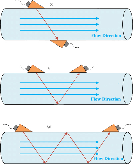
According to diameter of the pipe and the application of suitable conditions to record the passing time of signals of the sensors, three general types of installation are available for the sensors:

  • Type Z
  • Type V
  • Type W

***************

Type Z : 

When diameter of the pipe is large, this type of installation is used, which prevents the time movement of the ultrasonic wave inside the pipe and makes the sensor able to receive it and record the time of departure before the signal weakens.
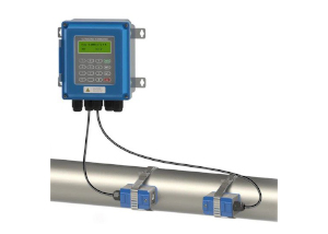
Type V :

This type of installation is used as a standard for small and medium-sized pipes, and during installation, in order to receive high quality ultrasonic signal, the exact location of the two sensors on the pipe must be specified. In this case, the signal emitted from one sensor first hits the lower wall of the tube and then is reflected to the second sensor.

One of the advantages of this method is that due to the small and medium diameter of the tube, the signal’s departure time is slightly increased to The system can be measured and also the sent signal reaches the receiving sensor with appropriate quality.

Type W :

When the diameter of the pipe is very small, this type of installation should be used so that the sent signal reaches the receiving sensor after several reflections in the pipe, so that the time of the signal’s departure is slightly increased, and for the signal device, the quality can be measured with